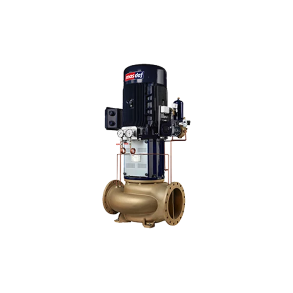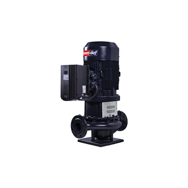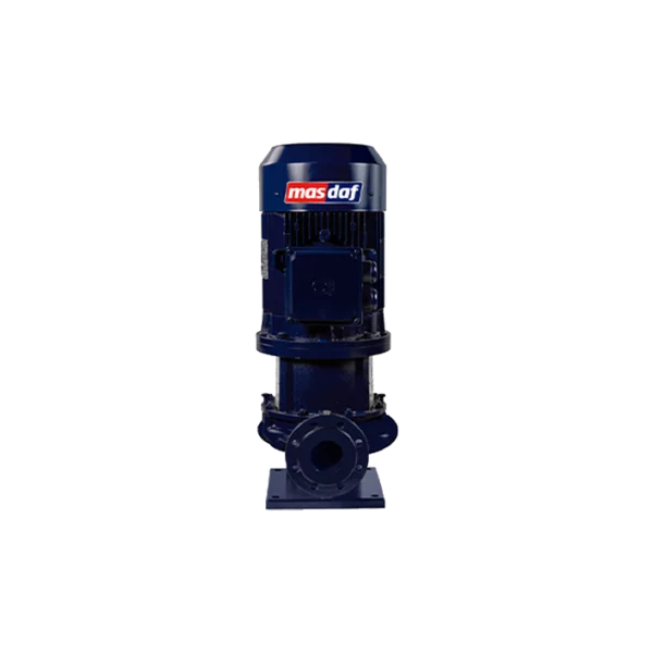
Masdaf - Circulation pumps (INMD)
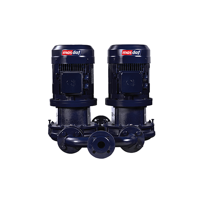
The INMD pump is a twin-stage, dry-rotor centrifugal pump. Flow rate: 2x(2–320) m³/h; head: 2 to 100 m; suction and discharge flanges DN 40–DN 125 on the same axis and of the same diameter, speed range 1,000–3,600 rpm, medium temperature from −25 to +120 °C.
INMD pump: how a twin-head pump is constructed
The series consists of two standard pumps combined INM using manifold components. The hydraulics of each half are identical to those in the single-pump version, hence the flow rate specification in the format 2x(2–320) m³/h: each pump provides its own range, whilst the common manifold combines them into a single pair of flanges.
This provides a single connection point to the pipeline instead of two separate pumps, each with its own piping, shut-off valves and a manifold that would have had to be fabricated on site.
The impeller in each half of the single-suction, closed-type pump is fitted with rear rings to counterbalance the axial load and is dynamically balanced.
INMD pump: the benefits of a non-return valve at the outlet of each pump
Check valves are integrated into the manifold — one at the outlet of each half.
Without them, the dual-system configuration would not operate in standby mode. When one pump is shut down and the other is running, the pressure in the common manifold is higher than the pressure in the shut-down section, and the flow would reverse through it — bypassing the network via a short circuit. The non-return valve prevents this.
The practical result is that the pumps operate independently of one another. If one fails, the other takes over, and the process continues uninterrupted. This is why a dual-system configuration is used for circuits where downtime is unacceptable.
INMD pump: technical specifications
| Parameter | Value |
|---|---|
| Type | linear centrifugal, twin, dry rotor |
| Levels | one for each half |
| Capacity | 2 × (2–320) m³/h |
| Pressure | 2–100 m |
| Revolutions | 1,000–3,600 rpm |
| Suction flange | DN 40–DN 125 |
| Discharge flange | DN 40–DN 125 |
| Flange positioning | on the same axis, of the same diameter |
| Medium temperature | −25…+120 °C |
| Pressure at the discharge flange | not exceeding 16 bar |
| Impeller | closed, single-sided suction, rear rings |
| Check valves | integrated, at the outlet of each pump |
| Motors | standard asynchronous |
When a twin pump is used instead of two separate ones
Two single pumps with manual switching provide the same backup configuration, but are more expensive to install: two sets of flanged connections, a separate manifold, two non-return valves as separate components, and a larger footprint.
The dual-unit design combines these into a single housing. The designer receives a ready-made assembly with a tested manifold hydraulic system, whilst the fitter receives a single pair of flanges.
Limits of application in the supply system. Each half of an INMD has a capacity of up to 320 m³/h, whilst a single INM has a capacity of up to 520 m³/h. Therefore, if a single operating point exceeding 320 m³/h is required, the twin-pump configuration is not suitable, and a redundancy system is designed using two separate pumps.
How to service the INMD pump
The back-pull-out design means that the rotor and impeller can be removed without dismantling the pipework — the casing and diffuser remain in the pipework.
The pump shaft is connected to the motor shaft by a special clamp, and this connection allows the pump to be removed without removing the motor.
This is particularly useful in a dual-system configuration: one half can be serviced whilst the other is in operation. The check valve at the outlet of the shut-down half maintains the pressure, ensuring that the network does not lose its supply whilst work is being carried out.
The motors in this series are standard induction motors, so they can be replaced without the need to specify a particular manufacturer.
Where is the INMD pump used?
The manufacturer lists water supply networks and pressure-boosting systems; irrigation, sprinkler systems and drainage; the circulation of hot or cold water in heating and cooling systems; the filling and emptying of reservoirs and tanks; and the pumping of fresh and seawater on ships.
The documentation for this series covers water circulation in swimming pools, industrial and public facilities.
A common feature of these applications is the requirement for continuity. A twin pump is installed where a shutdown of the circuit would mean a halt to the process or a loss of comfort at the site, rather than where a high flow rate is simply required.
Selection and service from Steiner Ukraine
For a twin-pump system, the selection is determined not only by the operating point but also by the operating mode of the two halves: one in operation and one on standby, or both operating in parallel with a switchover to a single pump when the flow rate decreases. The size of each half depends on this, as the parallel operation of two pumps on a shared circuit results in a total flow rate that is less than the arithmetic sum of their individual characteristics.
We determine the design flow rate and head, the system resistance characteristics, the selected redundancy mode, the ambient temperature, the available inlet head and the piping layout. Based on this, we determine the model size, flange diameters and actuator specifications. Next come supply, service and spare parts. Steiner Ukraine has been operating in the industrial equipment market since 2006.
The following helps to identify where energy is being lost in the existing system Energy audit of pumping stations. Single-stage version with motor drive — GenIO INM. Other items — in the section Masdaf pumps and in the catalogue industrial pumps and hydraulic systems.