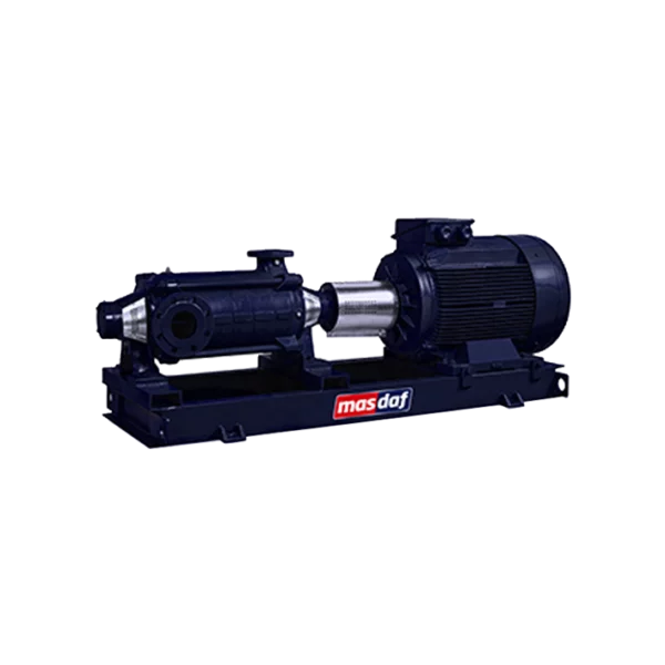
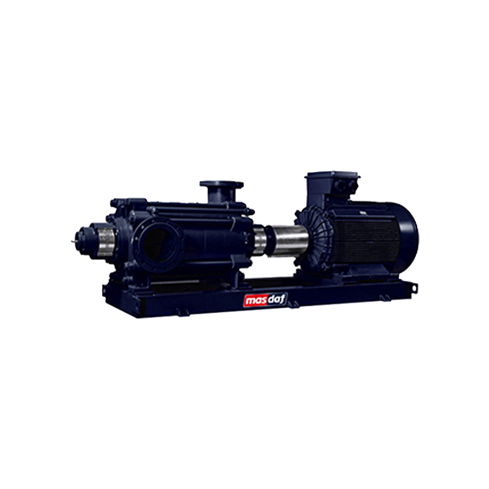
Masdaf – KME horizontal multistage pump
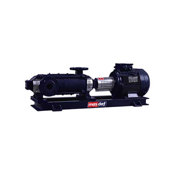
The KME multistage pump is a horizontal centrifugal pump of the sectional type with detachable stage casings, designed for an operating pressure of 40 bar. The series has a flow rate of 30 to 800 m³/h, a head of 30 to 480 m, and a speed of 1,500 to 1,800 rpm. The pump is not self-priming and operates with clean or slightly contaminated liquids at temperatures ranging from 0 to 110 °C.
How a sectional structure achieves a head of 480 metres
Each stage has its own casing, impeller and diffuser; the stages are assembled into a single unit on a common shaft. The fluid passes through them in sequence, with each subsequent stage increasing the outlet pressure of the previous one — thus achieving a head of up to 480 m. The number of stages is specified at the time of ordering, so a single model covers a wide range of head values without any changes to the hydraulics. Furthermore, the impellers can be machined to a specific operating point when the design head lies between two standard configurations.
How is the axial force balanced?
In a multistage pump, the axial forces from all the impellers combine and exert pressure on the shaft in one direction. At KME, these forces are counteracted in two stages. The main load is absorbed by wear rings and balancing holes behind the impeller. Where the pressure in the stages becomes high, the manufacturer additionally employs balancing discs and unloading drums. The shaft is supported by bearings on both sides of the impeller stack, so deflection is minimal.
How to interpret model codes
The notation is based on the following scheme KME 100 – 8, where KME is the series name, the first number is the nominal diameter of the discharge flange in millimetres, and the second is the number of stages. In other words, the KME 100–8 has a discharge flange with a DN of 100 and eight stages.
KME Technical Specifications
| Parameter | Value |
|---|---|
| Type | horizontal, multistage, centrifugal, sectional-type pump, non-self-priming |
| Working pressure | 40 bar |
| Capacity | 30 - 800 m³/h |
| Pressure | 30–480 m |
| Rotational speed | 1,500–1,800 rpm |
| Suction flange | DN 100 – DN 250 |
| Discharge flange | DN 80 – DN 200 |
| Flange standard | DIN 2535 |
| Fluid temperature | 0 – 110 °C |
| Impellers | single-flow, closed, dynamically balanced, with the option of machining to the operating point |
| Balancing the axial force | wear rings and balancing holes; for high-pressure stages — balancing discs and unloading drums |
| Bearings | 3300 series double-row radial-thrust ball bearings on the suction side; NU 300 series cylindrical roller bearings on the discharge side |
| Drive | electric motor mounted on a common frame via a flexible coupling |
| Direction of rotation | There are various options available |
| Certification | CE; TSE ‘Centrifugal Pump’, Classes 1 and 2 |
Which seal should I choose based on the ambient temperature?
| Implementation | Working limit |
|---|---|
| Packing without cooling (standard) | up to 90 °C |
| Mechanical seal without cooling | up to 90 °C |
| Water-cooled mechanical seal | from 90 to 140 °C |
| Double and cartridge mechanical seals | available as an option |
The specified temperature range for the series itself on the manufacturer’s website is 0–110 °C. Therefore, for operation above 90 °C, the seal design and the actual upper limit must be agreed with Masdaf on a case-by-case basis for each specific order.
What materials are available for the flow-through section?
| Part | Standard | Options |
|---|---|---|
| Suction and discharge casings | GG25 cast iron | GGG40, AISI 304, AISI 316, CuSn10 bronze |
| Stage housing | GG25 cast iron | GGG40, AISI 304, AISI 316, CuSn10 bronze |
| Impeller | GG25 cast iron | GGG40, AISI 304, AISI 316, CuSn10 bronze |
| Diffuser | GG25 cast iron | GGG40, AISI 304, AISI 316, CuSn10 bronze |
| Gland | GGG40 high-strength cast iron | AISI 304, AISI 316, CuSn10 bronze |
| Shaft and shaft sleeve | AISI 420 | AISI 304, AISI 316 |
| Gearbox | GG25 cast iron | GGG40, AISI 304, AISI 316, CuSn10 bronze |
| Bearing housing and cover | GG25 cast iron | GGG40 |
How to position the pipes during installation
In the standard configuration, when viewed from the motor side, the discharge casing is positioned on the motor side with the flange facing upwards, whilst the suction casing is positioned on the opposite side with the flange on the left. The flanges can be positioned on the left, right or top. On special request, the suction casing may be fitted on the motor side — in this case, the motor must rotate anti-clockwise. All other mounting options are available to order.
Where are KME pumps used?
- drinking water treatment plants and water distribution systems;
- increasing pressure in high-rise buildings and at industrial sites;
- water treatment and filtration plants;
- boiler feedwater and the condensate system;
- sanitary facilities and washing facilities;
- shipbuilding, the mining and energy sectors;
- irrigation;
- central heating systems.
When to choose the KME and when to choose the vertical KMEV
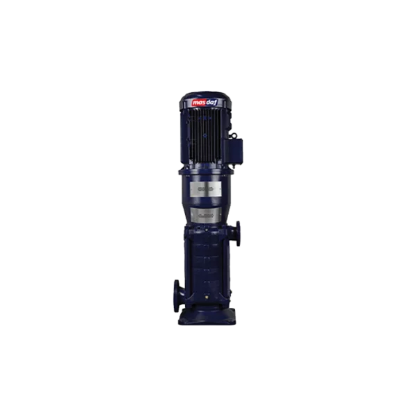
The hydraulic systems of both series are constructed in the same way: a sectional design, enclosed single-flow impellers, and the same materials. The difference lies in the layout and performance ranges. The KME is horizontal, with a capacity of up to 800 m³/h and a head of 480 m, featuring DN 100–250 flanges; it requires more floor space for the unit, but access to the seals and bearings is more convenient, and the number of stages can be greater. The KMEV is vertical, with a capacity of up to 300 m³/h and a head of 190 m, with flanges DN 125–150; it is chosen where space is limited. Rule of thumb: if there is sufficient length in the pump room, choose the KME; if only height is available, choose the KMEV.
Selection, supply and service from Steiner Ukraine
Two common mistakes when selecting a multistage pump are excessive head and an inappropriate number of stages: the former wastes electricity through throttling, whilst the latter shifts the operating point outside the range of maximum efficiency. To carry out the calculation, Steiner Ukraine requires: the nature and temperature of the fluid, the design flow rate and head, the suction pressure, material requirements, the available length for the unit and the required direction of rotation. Based on this data, we determine the KME model with the required number of stages, agree on the materials, seal type and pipe orientation, and provide a specification. Spare parts — impellers, diffusers, shaft sleeves, wear rings, seals and bearings — are ordered using the pump designation on the nameplate.