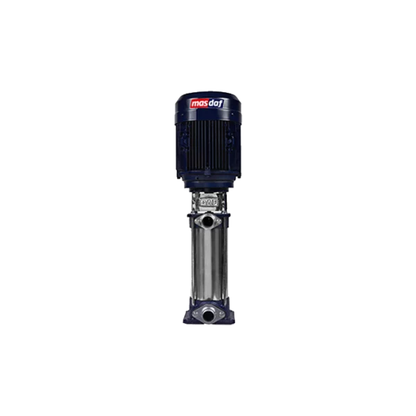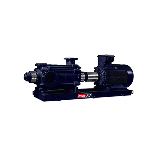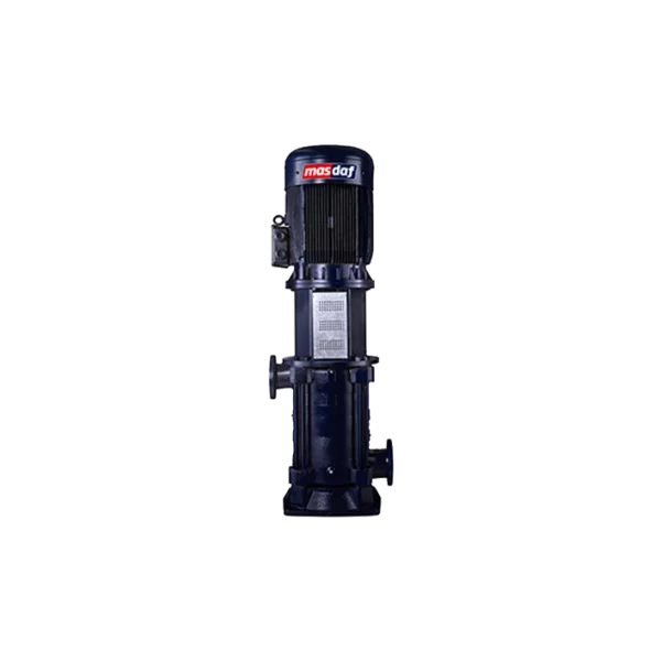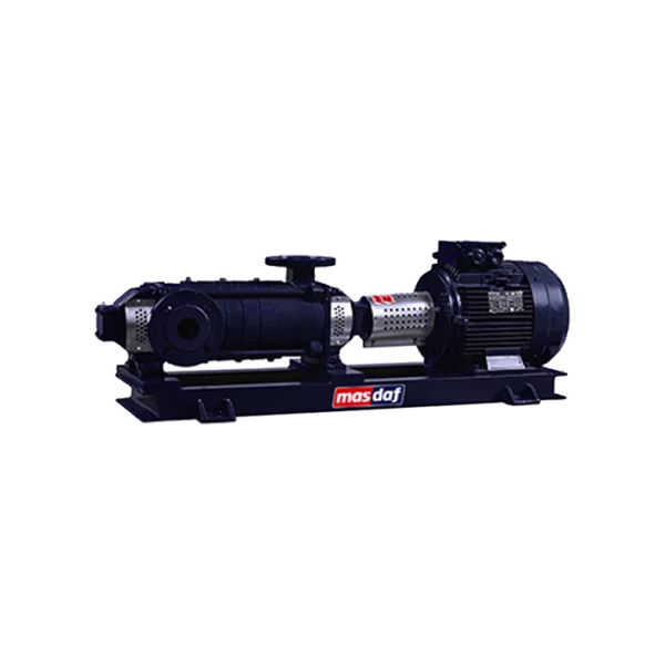
Masdaf – OMK horizontal multistage pump, 40 bar
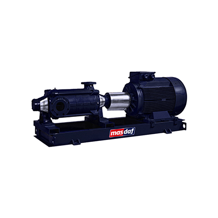
The OMK multistage pump is a horizontal centrifugal pump of the sectional type with split-case stages, designed for an operating pressure of 40 bar. The series has a flow rate ranging from 5 to 180 m³/h, a head ranging from 30 to 400 m, and a speed ranging from 1,500 to 3,600 rpm. The pump is not self-priming and is designed to handle clean or slightly contaminated liquids.
What applications is the OMK series designed for?
The OMK switches off the high-pressure mode at low flow rates: 400 metres of head at a flow rate starting from 5 m³/h. These parameters are required for pressure-boosting systems in high-rise buildings, boiler feed systems, washing installations, and industrial water distribution and irrigation systems. Unlike a vertical layout, a horizontal layout requires more floor space for the unit, but provides direct access to the gland, bearings and coupling without having to remove the pump from its base.
How to interpret model codes
The notation is based on the following scheme OMK 40–8, where OMK is the series designation, the first number is the nominal diameter of the pressure flange in millimetres, and the second is the number of stages. In other words, OMK 40–8 has a pressure flange of DN 40 and eight stages.
How is the load distributed along the shaft?
The axial force from the wheel assembly is counteracted by balancing holes in each working wheel, whilst the remainder is absorbed by the bearings. The shaft is supported on both sides by 6400 C3 ball bearings, which have different functions: the bearing on the suction side is fixed axially on the shaft and absorbs the residual axial load, whilst the bearing on the discharge side operates solely under radial load and is not axially fixed — this prevents the assembly from becoming ‘jammed’ due to thermal expansion of the shaft. A seal and a water deflector prevent water from entering the bearing housing.
OMK Technical Specifications
| Parameter | Value |
|---|---|
| Type | horizontal, multistage, centrifugal, sectional-type pump, non-self-priming |
| Working pressure | 40 bar |
| Capacity | 5 – 180 m³/h |
| Pressure | 30 – 400 m |
| Rotational speed | 1,500 – 3,600 rpm |
| Suction flange | DN 50 – DN 125, DIN 2535 (PN 40) |
| Discharge flange | DN 32 – DN 80, DIN 2535 (PN 40) |
| Fluid temperature | Rated temperature range for Series 0 – 110 °C; depending on the seal type – up to 110 °C with a packing seal, up to 140 °C with a mechanical seal |
| Impellers | single-flow, enclosed, between-support, dynamically balanced, with the option of machining to the operating point |
| Balancing the axial force | balancing holes; the residual force is absorbed by the bearing on the suction side |
| Bearings | 6400 C3 ball bearings on both sides; a seal and a water deflector at the inlet to the bearing housing |
| Wear rings | option |
| Drive | an electric motor mounted on a common base via a flexible coupling |
| Direction of rotation | By default, clockwise from the drive side; other options are available |
| Certification | CE; TSE ‘Centrifugal Pump’, Classes 1 and 2 |
Which seal should I choose based on the ambient temperature?
| Implementation | Working limit |
|---|---|
| Uncooled oil seal housing (standard) | up to 110 °C |
| Standardised single balanced mechanical seal without cooling | up to 140 °C |
The nominal temperature range for this series, as specified by the manufacturer, is 0–110 °C; therefore, versions designed for temperatures above 110 °C must be agreed with Masdaf on a case-by-case basis.
What materials are available for the flow-through section?
| Part | Standard | Options |
|---|---|---|
| Suction and discharge casings | GG25 cast iron | GGG40, AISI 304, AISI 316, CuSn10 bronze |
| Stage housing | GG25 cast iron | GGG40, AISI 304, AISI 316, CuSn10 bronze |
| Final-stage housing | GG25 cast iron | GGG40, AISI 304, AISI 316, CuSn10 bronze |
| Impeller | GG25 cast iron | GGG40, AISI 304, AISI 316, CuSn10 bronze |
| Gland | GGG40 high-strength cast iron | CuSn10 bronze |
| Shaft and shaft sleeve | AISI 420 | AISI 304, AISI 316 |
| Sealing cap | GG25 cast iron | GGG40, AISI 304, AISI 316, CuSn10 bronze |
| Bearing housing and cover | GG25 cast iron | GGG40 |
The standard version is designed for use with pure water. For treated boiler water and demineralised water, as well as other media that are corrosive to cast iron, the flow-through section should be ordered in stainless steel.
How to position the pipes during installation
In the standard configuration, the discharge casing is positioned on the motor side with the flange facing upwards, whilst the suction casing is positioned at the opposite end with the flange on the right-hand side when viewed from the drive side; the direction of rotation is clockwise. Both flanges can be oriented in 90° increments. On request, the suction housing can be fitted on the motor side — in which case the direction of rotation must be anti-clockwise when viewed from the drive side.
Where are OMK pumps used?
- drinking water treatment plants and water distribution systems;
- increasing pressure in high-rise buildings and at industrial sites;
- water treatment and filtration plants;
- boiler feedwater and the condensate system;
- sanitary facilities and washing facilities;
- shipbuilding, the mining and energy sectors;
- irrigation;
- central heating systems.
How does OMK differ from the vertical OMKV?
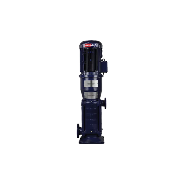
The hydraulic specifications are identical: the same 5–180 m³/h, 30–400 m, 40 bar, the same DN 50–125 and DN 32–80 flanges, and the same range of materials. What sets them apart is their layout and, consequently, the bearing assembly. The OMK horizontal model: the shaft rests on two 6400 C3 ball bearings; there is direct access to the gland and coupling, but the unit takes up a long section. OMKV (vertical): the same ball bearing is used at the top, whilst at the bottom there is a Teflon-coated bronze plain bearing, which is lubricated by the pumped liquid; the pump fits into a narrow space, but dry start-up is not permitted. The choice is determined by the geometry of the pump room and maintenance requirements.
Selection, supply and service from Steiner Ukraine
At a head of up to 400 metres, the operating point should fall within the zone of maximum efficiency: this point can be achieved through various combinations of the number of stages and impeller diameter, and the choice made will determine energy consumption throughout the entire service life. To carry out the calculation, Steiner Ukraine requires the following information: the nature and temperature of the fluid, the design flow rate and head, the suction pressure, material requirements, the available length for the unit and the required direction of rotation. Based on this data, we determine the OMK model with the required number of stages, agree on the materials, seal type and orientation of the connections, and provide a specification. Spare parts — impellers, stage housings, shaft sleeves, wear rings, packing and bearings — are ordered using the pump designation on the nameplate.